The relationship between the f-stops on your lens and your waveform display is a complex and inconsistent one. Phil Rhodes shines some light on something that should be theoretically straightforward... But isn't.
One of the best things about writing online is the opportunity to respond to questions in a way that helps everyone, and a good one was asked recently: how does the idea of f-stops relate to the shapes we see on a waveform monitor? Both are related to brightness, so yes, there is a relationship, but the bad news is that it's largely coincidental and not very consistent.
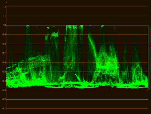
A waveform monitor
What's good about this is that it teaches us something about how brightness works in the modern world of digital cinematography, how cameras react to light, and how that light is encoded and displayed. If waveform monitors are an unfamiliar subject, it might be a good idea to have a look at this piece from earlier this year, on test and measurement, before going ahead.
A note on terminology
Before we dive into the details, let's clear up the technical terms. Often, particularly in the United States, the initialism IRE is used when referring to waveform monitors. The term comes from the Institute of Radio Engineers. Possibly the original definition relates to NTSC video, where signals cover a 1-volt range between -286 and 714 millivolts, between the highest peak white and the bottom of the synchronisation pulse (which goes lower than a black picture, so it's easy to detect). The range between zero and 714mV is divided into 100 units, although the decision to put NTSC black at 7.5 IRE or 53.57mV means that it's not quite accurate to consider IRE to be a percentage of maximum brightness. In PAL and the Japanese revision of NTSC, IRE more or less is a percentage, because those systems do place black at zero volts.
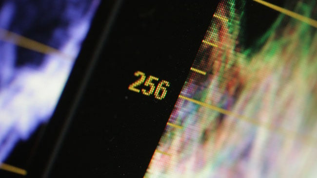
Some waveforms are calibrated in digital code values - here, 256 indicates 25% of full scale, but it may not always make much sense
None of this has much to do with modern digital video systems. There are still concerns over whether black and white are actually at the minimum and maximum code values in a file, though any discussion on mitigating that particular issue would fill an article on its own. Either way, digital waveform monitors are sometimes calibrated in code values, perhaps from zero to 1024, although that's equally nonsensical if we're working on material that wasn't 10-bit, to begin with. In the end, it's probably best to think of a waveform as simply showing a proportion of a maximum signal level. Even that becomes complicated in workflows involving HDR material, where “maximum” can mean such a wide variety of things, but it's a good enough approximation for right now.
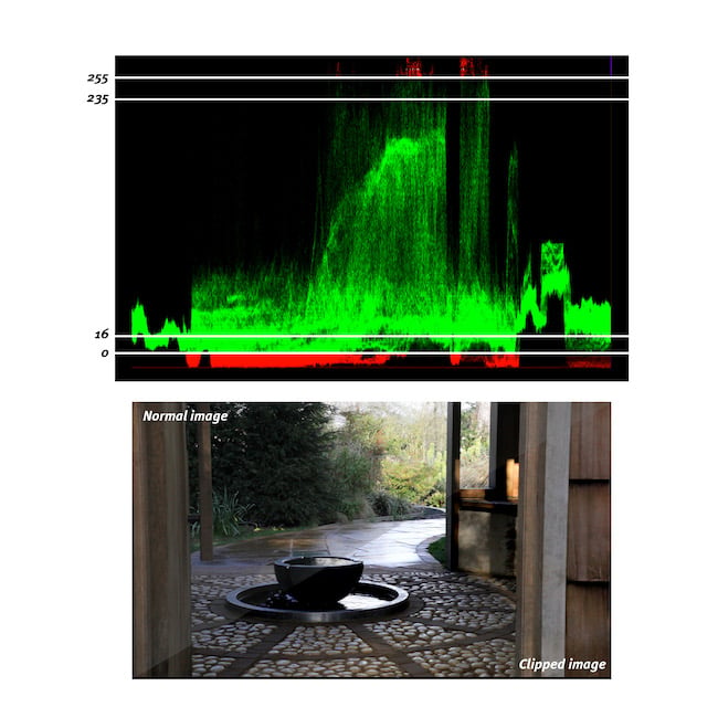
Here we see what happens when a file isn't properly processed for black and white levels - highlight and shadow detail can be lost. Note the diagonal split through the photographic image
F-stops and waveforms
First, let's define what an f-stop is: it's the ratio between the focal length and the size of the “entrance pupil,” which represents how much light makes it through the lens. A lower ratio effectively means we're looking through a shorter, fatter tube, which lets more light in; put crudely, a 50mm diameter tube that's 50mm long would have an f-number of 1.0. A longer, thinner tube naturally excludes more light and has a higher ratio; a 200mm long tube 20mm wide would have an f-number of 10.
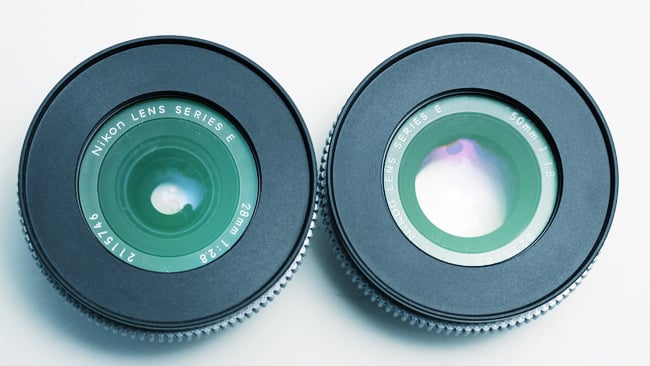
f-number is the ratio between the focal length and the entrance pupil, which basically means the hole through the lens as viewed through the front elements
The reason f-stops is a series of strange numbers is that the entrance pupil is generally roughly round, though it's often cropped into the shape of the lens iris, so we're talking about the area of a circle. Each stop represents a doubling of the area of that circle, and so a doubling of the light that makes it through the lens. That sounds simple enough: expose a grey card so that it appears on a waveform at 18%, open up a stop, and it should hit 36%, right?
Sadly, no. Well, not usually, anyway. It is possible to configure some cameras, mainly stills cameras, in a literal “linear light” mode, which would operate like that: the video signal level coming out of the camera, or encoded in its files, would directly represent the amount of light that hit the sensor. The problem with doing this quickly becomes obvious if we consider the implications. Take our 18% grey card and close down the lens to underexpose it a stop, and we have a signal level of 9%. Underexpose it a further stop and we have 4.5%, which is probably starting to disappear into the noise on many cameras, so let's say we have two stops of underexposure.
We could also overexpose the 18% grey card a stop, taking us to 36%. Overexpose a second stop and we're at 80%, and we can't overexpose a third stop because we can't have 160% of the maximum signal. With two stops underexposure and two and a quarter over, we have now defined a camera system with about 4.25 stops of dynamic range, which... well... no.
Linear light cameras?
This is why we don't usually make linear light cameras or at least if we do, we end up using very high bit-depth files to represent their data so there's lots of headroom. It's also part of the reason we don't usually expose 18% grey cards for 18% indication on a waveform monitor – 40 to 50 is more normal. The grey card is calculated to have the same brightness as the notionally average scene, so it's intuitive to place it around halfway up a waveform or a bit less.
In a linear light camera, that couldn't possibly work. If we place our 18% grey card at 50%, then open up a stop – if things operate linearly – then we have only one stop of overexposure space above middle grey. That's why things don't operate linearly. Our eyes are (approximately) logarithmic so that when we open up a stop, the image looks brighter; when we open up another stop, it looks brighter again, by a similar amount. What's actually happened is that the light level has doubled twice, but it looks like a regular increase in fixed steps to us.
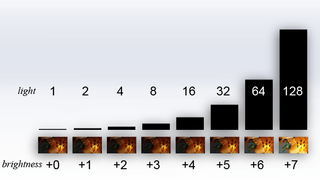
Top - the amount of light reaching the sensor. Bottom - what it looks like to humans, in f-stops
Because of that, what we actually do is store (something like) the base-2 logarithm of the linear signal or, in simpler terms, use the same amount of digital code values to store each doubling of the light level. For lots of information on this, look back at this piece on brightness encoding. If we did that literally, the waveform would be quite useful: if something appeared on a waveform at 50% and we opened up a stop, it might then appear at 60%. Open up another stop and it might appear at 70%. And yes, that is sort of roughly, approximately, how some modern cameras work sometimes. With a bit of tweaking, usually, in general. Often. Mostly.

When a waveform on a video monitor is being used, as here in the menu of a SmallHD 1303, a non-log signal is often being monitored, which generally breaks the relationship between f-stops and waveform displays
What breaks this relationship, at least slightly, is that different manufacturers like to tweak their cameras to look pretty. Once a colourist becomes involved and a monitor is being used to view a picture that's been creatively tweaked, all bets are off, and this is why different manufacturers refer to Log C (Arri), SLog (Sony), Vlog (Panasonic) and many others. So, are a waveform and a lens's f-stop related? Sort of. It works to a degree if the waveform is showing a log signal and especially if a setup is tested thoroughly at camera checkout. If LUTs are being used, or if we're monitoring any signal intended for viewing, such as one prepared for a Rec.709 display, great caution is required, as the relationship between stops and waveform percentages will be very strange.
Tags: Production


Comments